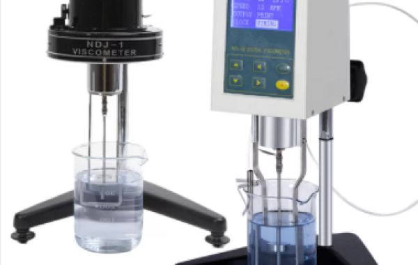
With a wide range of testing, easy operation, and simple maintenance, the lab rotational viscometer is one of the most important methods of fluid viscosity measurement.
In the actual production, application, and testing process of the viscometer, the rotor constant is often used as a constant value, and the standard solution is used to calibrate under a certain parameter, and then the full range is used.
This holds true when the lab rotational viscometer gap flow state is in the ideal constant laminar flow state, and in practice its gap flow state is complex.
The influence of the interstitial flow pattern of the lab rotational viscometer on the viscosity test should not be neglected. For this reason, the interstitial flow was simulated using AnsysFluent analysis software, and the difference in the interstitial flow pattern at different gap ratios and rotational speeds was analyzed. The deviation of the measured values of the viscometer at different rotational speeds was tested, and suggestions were made for the standardized operation of the lab rotational viscometer.
Lab Rotational Viscometer Working Theory
When a lab rotational viscometer is in operation, the rotor rotates around the central axis under the action of an external force F, which drives the flow of the interstitial fluid, and the forces are balanced when the system maintains a uniform rotation of the rotor, as shown in Figure 1. The rotor is subjected to the force F from maintaining the rotor rotation and the shear stress Fτ generated by the fluid is measured due to the viscous nature, and the viscosity value of the interstitial fluid can be measured by measuring the force F. This is the formula for calculating the viscosity value of the rotational method viscometer:


In equation (1): M-torque, N. m; ω-angular velocity, rad /s; h- length of the inner column, m; c- additional tube length due to end effect, m; r- radius of the inner column, m; R -internal radius of the outer column, m.
Deformation of equation ( 1):
")
In the equation: TK - viscometer torque constant; SMC - rotor constant; RPM - angular velocity, r/min; ε - clearance ratio.
The calibration of the lab rotational viscometer is actually a correction of the SMC value of the viscometer. In the actual application of the viscometer, the SMC value is often taken as a constant value, and the standard liquid is used for full range after calibration under a certain parameter. The following problems exist: ( 1) Equation ( 1) is derived under the assumption that the interstitial flow is in a constant laminar flow state, which is not guaranteed under the actual operating conditions. ( 2) From equation ( 2), the inner and outer rotor clearance ratio and rotational speed affect the SMC value, and it is not accurate to treat the SMC value as the same constant under different parameters.
Lab Rotational Viscometer Settings
When the lab rotational viscometer works, the inner and outer cylinders are coaxial, and the rotor drives the gap flow to do an encircling motion. This model is similar to the mechanical bearing lubrication, engine air gap simplification model, and other fluid machinery, which is called the Taylor Cottage flow model. In order to explore the rotary viscometer gap ratio, rotational speed affects the gap flow state and then reacts to the different values of viscosity measurement. The gap ratio and rotational speed are used as variables to model the gap flow model, respectively.
(1) Different Gap Ratios
Geometric model: Rotor radius 10mm, speed 30r/min, height 100mm, gap ratio 1. 0 and 0. 4. Game-bit2. 2 is used to draw the mesh, the radial mesh is encrypted in both directions, ratio 1. 05, axial and circumferential are uniform mesh. AnsysFluent6. 3 was used with the same physical parameters. After convergence, the tangential velocity cloud is analyzed and the axial cross-section of the inner and outer rotor gap is intercepted, as shown in Figure 2.

Figure 2a The gap ratio is 1. 0, and in Figure 2b The gap ratio is 0. 4. The flow of the gap flow is stable when the gap is relatively large, and the velocity decreases gradually from the inside to the outside and becomes uniformly distributed. The tangential velocity distribution in the radial direction is shown in Figure 3. The slope of the velocity distribution curve is basically constant, which further indicates that the tangential velocity distribution in the radial direction is uniform and the flow of the gap fluid is stable without disturbance and laminar flow pattern. Figure 2b, the gap ratio changes the flow state of the gap flow changes greatly, and the vortex is obvious at this parameter.

(2) Different Rotation Speed
Geometric model: The radius of the rotor is 10mm, the height is 100mm, the clearance ratio is 0. 4, and the speed is 5r/min and 30r/min. The results are shown in Figure 4.
As shown in Figure 4a, the flow of the interstitial flow is stable when the speed is small, no disturbance appears, and the flow state is laminar. After the speed increases, the flow state of the interstitial flow changes, and the disturbance becomes more and more intense, as in Figure 4b.
The change of gap ratio and rotational speed changes the flow pattern of gap flow, and the flow pattern affects the internal stress of gap flow on the rotor, which is presented as different viscosity measurement values. In addition, the influence factors are more complicated in the actual working process of rotational viscometers, such as end effect, axis offset, etc. will lead to the change of gap flow pattern, as shown in Figure 5. Therefore, in the actual production, application, and testing of viscometers, theoretically, the SMC value should be corrected under each variable parameter.


Lab Rotational Viscometer Experiment
Lab rotational viscometer instrument parameters (e.g., rotational speed, gap ratio) affect the viscosity measurements. To further investigate the differences in viscosity measurements under different instrument parameters, tests were conducted with rotational speed as the variable.
Rotor No. 1 of BROOKFIELD model DV2TLVTJ0 was used to test the secondary standard viscosity fluid at different speeds. In accordance with JJG1002 - 2005 "Lab Rotational Viscometer Calibration Procedure", 200# secondary standard viscosity fluid (222.7MPa.s, 20℃) was selected and tested twice according to decreasing and increasing speed, and the results are shown in Table 1. Technical conditions: temperature ( 20 ~ 21) ℃, relative humidity ( 55 ~ 60) % RH, temperature fluctuation of 0. 05 ℃ /15min in the constant temperature bath, digital thermometer scale value 0. 01 ℃. The deviation of the measured value is 1. 5%.
Table1 Viscosity Test Results
| Rotational Speed(r/min) | Torque Percentage(%) | Display Value (MPa. s) | Rotational Speed(r/min) | Torque Percentage(%) | Display Value (MPa. s) |
| 5 | 18.3 | 219. 2 | 25 | 87.4 | 222.0 |
| 10 | 36.1 | 218.9 | 20 | 70.1
| 221.9 |
| 15 | 55.1 | 220.3 | 15 | 54.8 | 220.1 |
| 20 | 70.1 | 221.9 | 10 | 36.2 | 219.0 |
| 25 | 87.9 | 222.2 | 5 | 18.3 | 219.2 |
The secondary standard viscosity fluid was tested at different rotational speeds using rotor No. 5 of BROOKFIELD model DV2TRVTJ0. The results are shown in Table 2, with the same technical conditions and test procedure. The deviation of the measured values was 1. 0%.
Table2 Viscosity Test Results
| Rotational Speed(r/min) | Torque Percentage(%) | Display Value (MPa. s) | Rotational Speed(r/min) | Torque Percentage(%) | Display Value (MPa. s) |
| 45 | 93.1 | 8276 | 10 | 20.9 | 8362 |
| 40 | 82.8 | 8280 | 15 | 31.2 | 8337 |
| 35 | 72.6 | 8297 | 20 | 41.7 | 8340 |
| 30 | 62.3 | 8307 | 25 | 52.0 | 8320 |
| 25 | 52.0 | 8320 | 30 | 62.3 | 8307 |
| 20 | 41.7 | 8340 | 35 | 72.6 | 8297 |
| 15 | 31.3 | 8347 | 40 | 82.9 | 8290 |
| 10 | 20.9 | 8360 | 45 | 93.1 | 8276 |
Lab Rotational Viscometer Gap Flow Effect Conclusion
Changes in the gap ratio and rotational speed of the lab rotational viscometer lead to different flow patterns of the gap flow, and the changes in flow patterns affect the viscosity measurement values. Experiments have shown that the deviation of the instrument value at different rotational speeds is up to 1. 5%, and the sample flow pattern and its influence on the viscosity measurement should not be ignored. Therefore, in the actual production, application, and testing process, Therefore, it is not advisable to use the SMC value as a constant value in the actual production, application, and testing process, and to use the standard solution for the full range after calibration under a certain parameter.
It is recommended to make SMC value corrections for different parameters during the calibration of the lab rotational viscometer according to the actual needs of the customer and to ensure that the same parameters are used in the application.